Hertzian contact
Click on Solid Mechanics to go back.
Contents
Contact of Cylinders - the Hertz problem
Detailed discussions of this problem can be found in Hills and Nowells (1994) as well as Williams and Dwyer-Joyce (2001). [1] [2]
If two circular cylinders with radii $R_1$ and $R_2$ are pressed together by a force per unit length of magnitude $P$ with their axes parallel, then the contact patch will be of half-width $b$ such that \begin{equation} b = 2\sqrt{\frac{PR}{\pi E^*}} \end{equation} where $R$ and $E^*$ are the reduced radius of contact and the contact modulus defined by \begin{equation} \frac{1}{R} = \frac{1}{R_1} + \frac{1}{R_2}, \end{equation} \begin{equation} \frac{1}{E^*} = \frac{1-{\nu_1}^2}{E_1} + \frac{1-{\nu_2}^2}{E_2}. \end{equation}
The resulting pressure distribution $p(x)$ is semielliptical, i.e., of the form \begin{equation} p(x) = p_0 \sqrt{1-\frac{x^2}{b^2}} \end{equation} where the peak pressure \begin{equation} p_0 = \sqrt{\frac{PE^*}{\pi R}}. \end{equation}
The coordinate $x$ is measured perpendicular to that of the cylinder axes. The cylinder is pressing on the lower halfplane from above. Analytical solutions for stresses in the plane are presented below. The coordinate ranges are $x \in (-\infty, \infty), z\in (-\infty, 0]$.
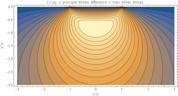
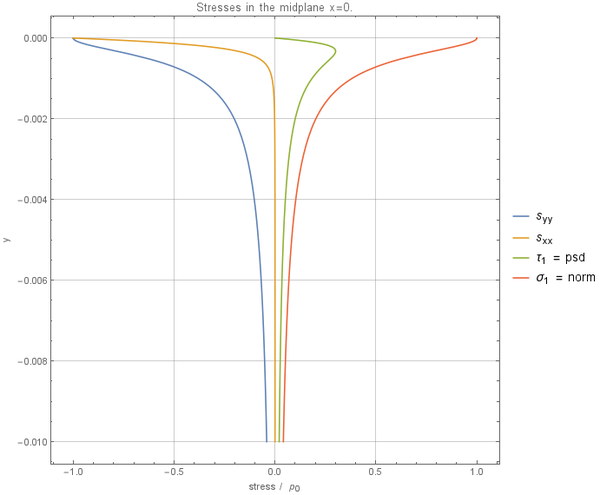
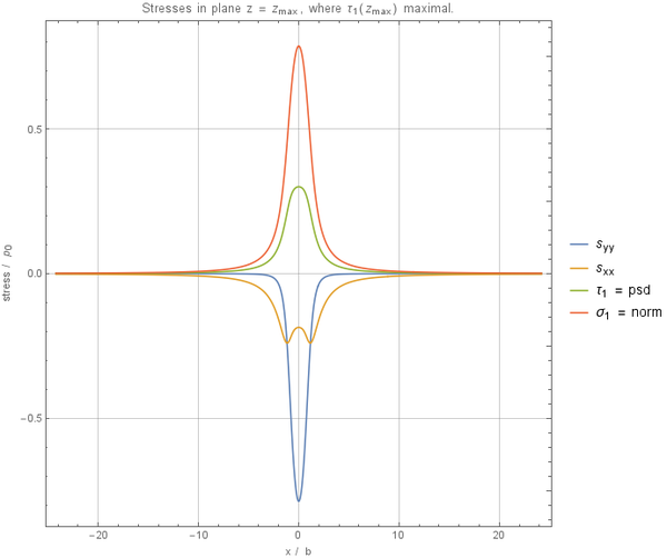
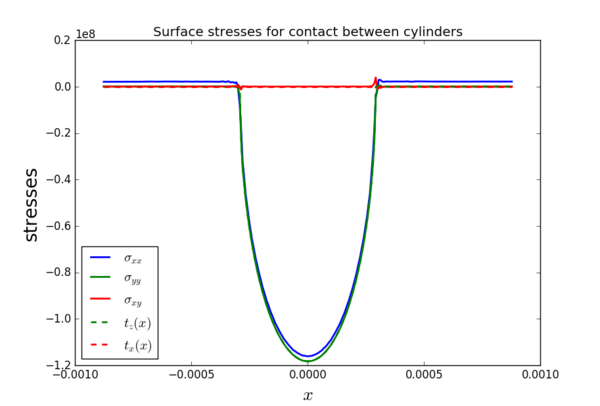
The surface stresses are given in the following equations. At the contact interface \begin{equation} \sigma_{xx} = \sigma_{zz} = -p(x); \end{equation} outside the contact region all the stress components at the surface are zero. Along the line of symmetry the following equations hold \begin{equation} \sigma_{xx} = -p_0\left( \frac{1+(z/b)^2}{\sqrt{1+(z/b)^2}} + 2z/b\right) \end{equation} \begin{equation} \sigma_{zz} = -p_0(1 + z^2/b^2)^{-1/2} \end{equation} These are the principal stresses so that the principal shear stress $\tau_1$ is given by \begin{equation} \tau_1 = -p_0\left(z/b + \frac{(z/b)^2}{\sqrt{1+(z/b)^2}}\right) \end{equation} from which \[(\tau_1)_\mathrm{max} = 0.30p_0, \quad \text{at } z = 0.78b\]
Note that these stresses are all independent of Poisson's ratio although, for plane strain, the third principal stress \[\sigma_{yy} = \nu(\sigma_{xx} + \sigma_{zz}). \]
At a general point $(x,z)$ the stresses may be expressed in terms of $m$ and $n$, defined by
\begin{equation}
m^2 = \frac{1}{2} \left(\sqrt{\left(b^2-x^2+z^2\right)^2+4 x^2 z^2}+b^2-x^2+z^2\right)
\end{equation}
\begin{equation}
n^2 = \frac{1}{2} \left(\sqrt{\left(b^2-x^2+z^2\right)^2+4 x^2 z^2}-(b^2-x^2+z^2)\right)
\end{equation}
with $m = +\sqrt{m^2}$ and $n = \operatorname{sgn}(x)\sqrt{n^2}$.
Whereupon
\begin{equation}
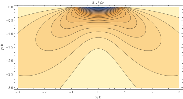
\sigma_{xx} = -\frac{p_0}{b}\left[m\left(1 + \frac{z^2 + n^2}{m^2 + n^2}\right)+2z\right]
\end{equation}
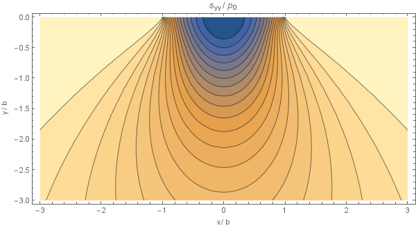
\begin{equation} \sigma_{zz} = -\frac{p_0}{b}m\left(1 - \frac{z^2 + n^2}{m^2 + n^2}\right) \end{equation}
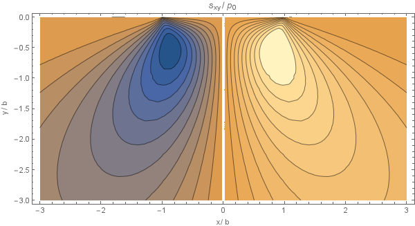
\begin{equation} \sigma_{xz} = \sigma_{zx} = \frac{p_0}{b}n\left(\frac{m^2 - z^2}{m^2 + n^2}\right) \end{equation}
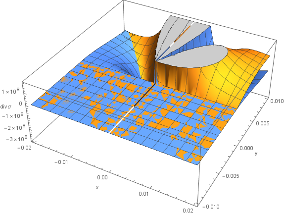
Plots of this analytical solution are presented below, using $p_0 = 8.36\cdot10^{7}, b = 4.13\cdot10^{-4}$
The solutions were verified and graphs were generated using this mathematica notebook: File:hertzian_analytical.nb Copy-pasteable Matlab code:
 1 function [sxx, syy, sxy] = analytical(x, z, b, p0)
 2 % Returns the analytical solution for stress for hertzian contact.
 3 % x in (-inf, inf), z in (-inf, 0].
 4 bxz = b^2 - x.^2 + z.^2;
 5 xz = 4*x.^2.*z.^2;
 6 koren = sqrt(bxz.^2 + xz);
 7 m2 = 1/2 * (koren + bxz);
 8 n2 = 1/2 * (koren - bxz);
 9 m = sqrt(m2);
10 n = sign(x) .* sqrt(n2);
11 mpn = m2 + n2;
12 zmn = (z.^2 + n2) ./ mpn;
13 sxx = -p0 / b * (m .* (1 + zmn) + 2*z);
14 syy = -p0 / b * m .* (1 - zmn);
15 sxy = p0 / b * n .* ((m2 - z.^2) ./ mpn);
16 end
The extreme of $\tau_1$ is achieved at $x = 0$, $z = -\sqrt{\frac{1}{2} \left(\sqrt{5}-1\right)} b = -0.786b$.
When observing for $z \to -\infty$ it holds that $s_{xx} = \frac{\frac{b^3 p_0}{4}+b p_0 x^2}{z^3}+O(z^{-5})$, $s_{zz} = \frac{b p_0}{z}-\frac{b p_0 \left(b^2+4 x^2\right)}{2 z^3}+O(z^{-5})$, $s_{xz} = \frac{b p_0 x}{z^2}+\frac{-\frac{3}{2} b^3 p_0 x-2 b p_0 x^3}{z^4}+O(z^{-5})$.
When observing for $x \to \infty$ (and similarly for $-\infty$) it holds that
$s_{xx} = \frac{b p_0 z}{x^2}+\frac{\frac{3}{4} b^3 p_0 z-2 b p_0 z^3}{x^4}+O(x^{-5})$, $s_{zz} = \frac{b p_0 z^3}{x^4}+O(x^{-5})$, $s_{xz} = \frac{b p_0 z^2}{x^3}+O(x^{-5})$.
Contact of cylinders under partial slip
The second case we study is the application of a tangential force $Q$ to the previous problem. When the tangential force is less than the limiting force of friction, i.e., \[|Q| < \mu P,\] where $\mu$ is the coefficent of friction, sliding motion will not occur but the contact will be divided into regions of slip and stick zones that are unknown a priori. For the case of cylinders the analysis is given in Hills & Nowell (1994), p. 44.
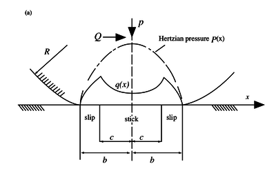
Besides the normal traction $p(x)$ we know have an additional shear traction given by \begin{equation} q(x) = \begin{cases} -\mu p_0 \sqrt{1 - \frac{x^2}{b^2}}, \quad c \leq |x| \leq b \\ -\mu p_0 \left(\sqrt{1 - \frac{x^2}{b^2}} - \frac{c}{b}\sqrt{1 - \frac{x^2}{c^2}}\right), \quad |x| < c \end{cases} \end{equation} where $b$ is the half-width of the whole contact, and $c$ the half-width of the central sticking region. The width of the central zone, i.e. the value of dimension $c$ is dependent on the applied tangential force $Q$: \begin{equation} \frac{c}{b} = \sqrt{1 - \frac{Q}{\mu P}} \end{equation}
The distributions $q(x)$ and $p(x)$ as well as the widths of the stick and slip zones can be seen in the image below.
The effect of bulk stress
Additionally we might be interested in the addition of bulk stress. This type of stress occurs in fretting fatique experiments like the one shown below.
The previous solution for contact of cylinders under partial slip can be adjusted for the presence of bulk stresses $\sigma_\mathrm{axial}$. These cause an eccentricity $e$ to the solution given above. The shear traction $q(x)$ can be written as: \begin{equation} q(x) = \begin{cases} -\mu p_0 \sqrt{1 - \frac{x^2}{b^2}}, \quad c \leq | x - e | \text{ and } |x| \leq b \\ -\mu p_0 \left[\sqrt{1 - \frac{x^2}{b^2}} - \frac{c}{b}\sqrt{1 - \frac{(x-e)^2}{c^2}}\right], \quad |x-e| < c \end{cases} \end{equation} where once again \[ \frac{c}{b} = \sqrt{1 - \frac{Q}{\mu P}}\] and \begin{equation} e = \frac{b \sigma_\mathrm{axial}}{4 \mu p_0}. \end{equation} If larger values of $\sigma_\mathrm{axial}$ are applied, one edge of the stick zone will approach the edge of the contact ($e$ becomes larger). The solution for the shear stress traction is therefore only valid if $e + c \leq b$, i. e. \[\frac{\sigma_\mathrm{axial}}{\mu p_0} \leq 4\left(1 - \sqrt{1 - \frac{Q}{\mu P}}\right).\]
FreeFem++ numerical solution
For the numerical solution in FreeFem++ we choose parameters similar to those in Pereira et al. (2016): [3]
- Modulus of elasticity: $E = 72.1$ GPa
- Poisson's ratio: $\nu = 0.33$
- Normal load: $P = 543$ N
- Coefficient of friction: $\mu = 0.85$
- Cylinder radius: $R = 50$ mm
- Specimen length: $L = 40$ mm
- Specimen height: $H = 10$ mm
We assume that both the pad and specimen are from the same material, therefore the combined modulus is \[E^* = \frac{E}{2(1-\nu^2)}.\] According to Pereira et al. (2016) contact width is now defined with the specimen height in the denominator: \[b = 2\sqrt{\frac{PR}{H\pi E^*}}\] \[p_0 = \sqrt{\frac{PE^*}{H\pi R}}\]
(this might not be correct, because $p_0$ should be equal to $2P/(\pi b)$? Does $R/H$ perhaps represent a dimensionless radius?)
Out of simplicity we only use traction boundaries at the top surface. On the left, right and bottom sides of the specimen Dirichlet boundaries are used. The center of the coordinate system is placed at $(x,y) = (L/2,0)$. The axises therefore go from $-L/2$ to $L/2$ in $x$-direction and from $0$ to $H$ in $y$-direction.
                top
      ________________________
     |                        |
     |                        |
left |                        | right
     |                        |
     |________________________|

               bottom
Boundary conditions: \[ t_z(x) = \begin{cases} -p_0\sqrt{1 - \frac{x^2}{b^2}}, \quad |x| \leq b \\ 0, \quad \text{otherwise} \end{cases} \quad \text{on } \Gamma_\mathrm{top} \] \[ (u_x,u_z) = (0,0) \quad \text{on } \Gamma_\mathrm{left},\Gamma_\mathrm{right},\Gamma_\mathrm{bottom} \]
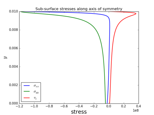
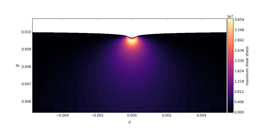
The numerical solution is obtained for plane strain conditions using quadratic finite elements. The final mesh after adaptation had ~$40000$ dof. The images below show the raw values of the surface stresses, sub-surface stresses along the axis of symmetry and a close-up of the maximum shear stress contours close to the contact. The contact width $b \approx 0.29$ mm for the parameters described at the beginning of this section.
MLSM numerical solution
Problem parameters used:
- Modulus of elasticity: $E = 72.1$ GPa
- Poisson's ratio: $\nu = 0.33$
- Normal load: $P = 543$ N
- Coefficient of friction: $\mu = 0.85$
- Cylinder radius: $R = 50$ mm
- Specimen length: $L = 40$ mm
- Specimen height: $H = 20$ mm
The boundary conditions are zero except for the top layer which has zero traction in $x$ direction and traction $t_z$ in $z$ direction. The solution matches the analytical solution well. 800px
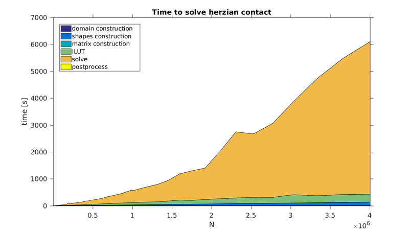
Execution time is shown below. Program ran on a single core. Most of the time is spent on solving the system of the equations.
The error decreases as the density of nodes increases, up to some limit when the system becomes too unstable. 800px
References
- ↑ Hills, D. A. and Nowell, D. (1994). Mechanics of Fretting Fatique, p. 20-25. Springer Science+Business Media, Dordrecht.
- ↑ Williams, John A. and Dwyer-Joyce, Rob S. (2001). Contact Between Solid Surfaces, p. 121 in Modern Tribology Handbook: Volume 1, Principles of Tribology, editor: Bushan, Bharat. CRC Press LLC, Boca Raton.
- ↑ Pereira et al. (2016). On the convergence of stresses in fretting fatique. Materials, 9, 639.
