Difference between revisions of "Fretting fatigue case"
(→Case definition) |
(→Case definition) |
||
| Line 52: | Line 52: | ||
We are solving the equation $$(\lambda + \mu) \nabla (\nabla \cdot \b{u}) + \mu \nabla^2 \b{u} = 0$$ | We are solving the equation $$(\lambda + \mu) \nabla (\nabla \cdot \b{u}) + \mu \nabla^2 \b{u} = 0$$ | ||
| − | on the domain $D = [-L/2, L/2] \times [- | + | on the domain $D = [-L/2, L/2] \times [-W/2, 0]$. Componentwise $\b{u} = [u; v]$. |
The boundary conditions are: | The boundary conditions are: | ||
* top: $\vec{t}(x) = (q(x), -p(x))$ or componentwise $\mu \frac{\partial u}{\partial y}(x, 0) + \mu \frac{\partial v}{\partial x}(x, 0) = q(x)$ and $(2 \mu+\lambda) \frac{\partial u}{\partial x}(x, 0) + \lambda \frac{\partial v}{\partial y}(x, 0) = -p(x)$ . | * top: $\vec{t}(x) = (q(x), -p(x))$ or componentwise $\mu \frac{\partial u}{\partial y}(x, 0) + \mu \frac{\partial v}{\partial x}(x, 0) = q(x)$ and $(2 \mu+\lambda) \frac{\partial u}{\partial x}(x, 0) + \lambda \frac{\partial v}{\partial y}(x, 0) = -p(x)$ . | ||
Revision as of 07:47, 3 October 2017
Click on Solid Mechanics to go back.
Contents
Theoretical introdution
This case is an extension of the classical Hertzian contact, as defined in Pereira et al. (2016) [1] and described in detail in Hojjati-Talemi et al. (2014) [2]
Contact of cylinders under partial slip
This extends the classical theory of Hertzian contact with a tangential force $Q$. When the tangential force is less than the limiting force of friction, i.e., \[|Q| < \mu P,\] where $\mu$ is the coefficent of friction, sliding motion will not occur but the contact will be divided into regions of slip and stick zones that are unknown a priori. For the case of cylinders the analysis is given in Hills & Nowell (1994), p. 44.
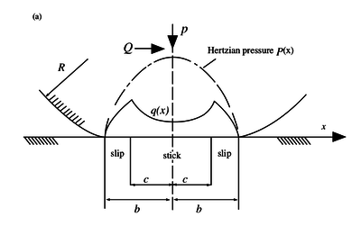
Besides the normal traction $p(x)$ we know have an additional shear traction given by \begin{equation} q(x) = \begin{cases} -\mu p_0 \sqrt{1 - \frac{x^2}{b^2}}, & c \leq |x| \leq b \\ -\mu p_0 \left(\sqrt{1 - \frac{x^2}{b^2}} - \frac{c}{b}\sqrt{1 - \frac{x^2}{c^2}}\right), & |x| < c \end{cases} \end{equation} where $b$ is the half-width of the whole contact, and $c$ the half-width of the central sticking region. The width of the central zone, i.e. the value of dimension $c$ is dependent on the applied tangential force $Q$: \begin{equation} \frac{c}{b} = \sqrt{1 - \frac{Q}{\mu P}} \end{equation}
The distributions $q(x)$ and $p(x)$ as well as the widths of the stick and slip zones can be seen in the image below.

The effect of bulk stress
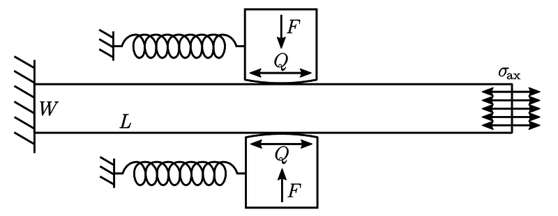
Additionally we might be interested in the addition of bulk stress $\sigma_{\textrm{ax}}$. This type of stress occurs in fretting fatique experiments like the one shown below [1].
The previous solution for contact of cylinders under partial slip can be adjusted for the presence of bulk stresses $\sigma_\mathrm{ax}$. These cause an eccentricity $e$ to the solution given above. The shear traction $q(x)$ can be written as: \begin{equation} q(x) = \begin{cases} -\mu p_0 \sqrt{1 - \frac{x^2}{b^2}}, \quad c \leq | x - e | \text{ and } |x| \leq b \\ -\mu p_0 \left[\sqrt{1 - \frac{x^2}{b^2}} - \frac{c}{b}\sqrt{1 - \frac{(x-e)^2}{c^2}}\right], \quad |x-e| < c \end{cases} \end{equation} where once again \[ \frac{c}{b} = \sqrt{1 - \frac{Q}{\mu F}}\] and \begin{equation} e = \frac{b \sigma_\mathrm{ax}}{4 \mu p_0}. \end{equation} If larger values of $\sigma_\mathrm{ax}$ are applied, one edge of the stick zone will approach the edge of the contact ($e$ becomes larger). The solution for the shear stress traction is therefore only valid if $e + c \leq b$, i. e. \[\frac{\sigma_\mathrm{ax}}{\mu p_0} \leq 4\left(1 - \sqrt{1 - \frac{Q}{\mu F}}\right).\]
MLSM numerical solution for FWO case
We replicate the numerical solution described in Pereira et al. (2016) [1]
Case definition
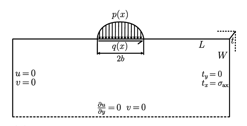
We are solving the equation $$(\lambda + \mu) \nabla (\nabla \cdot \b{u}) + \mu \nabla^2 \b{u} = 0$$ on the domain $D = [-L/2, L/2] \times [-W/2, 0]$. Componentwise $\b{u} = [u; v]$. The boundary conditions are:
- top: $\vec{t}(x) = (q(x), -p(x))$ or componentwise $\mu \frac{\partial u}{\partial y}(x, 0) + \mu \frac{\partial v}{\partial x}(x, 0) = q(x)$ and $(2 \mu+\lambda) \frac{\partial u}{\partial x}(x, 0) + \lambda \frac{\partial v}{\partial y}(x, 0) = -p(x)$ .
- left: $\b{u} = 0$ or componentwise $u(-L/2, y) = v(-L/2, y) = 0$.
- bottom: up-down symmetry conditions: componentwise $\frac{\partial u}{\partial y}(x, -H/2) = 0, v(x, -H/2) = 0$.
- right: this part is traction free, ie. $\vec{t}(y) = 0$ or componentwise $\mu \frac{\partial u}{\partial y}(L/2, y) + \mu \frac{\partial v}{\partial x}(L/2, y) = 0$ and $(2 \mu+\lambda) \frac{\partial v}{\partial y}(L/2, y) + \lambda \frac{\partial u}{\partial x}(L/2, y) = 0$.
Illustration of the computational domain is presented below.
Phsyical parameters
Basic parameters are:
- $E = \unit{72.1}{GPa}$, Youngs modulus
- $\nu = 0.33$, Poissons ratio
- $L = \unit{40}{mm}$, length, width of the pad
- $H = \unit{4}{mm}$, height, thickness of the pad
- $\sigma_{ax} = \unit{100}{MPa}$, axial pressure
- $F = \unit{543}{N}$, normal force
- $Q = \unit{155}{N}$, tangential force
- $R = \unit{10}{mm}$ or $\unit{50}{mm}$, raduis of curvature of the cylindrical pad
- $COF = \mu = 0.3$ or $0.85$ or $2$, coefficient of friction
Derived parameters are, for choice of $R = \unit{10}{mm}$ and $\mu = 0.3$:
- $E^\ast = \frac{E}{2(1-\nu^2)} = \unit{40.4}{GPa}$, combined Young's modulus
- $p_{max} = p_0 = \sqrt{\frac{FE^\ast}{HR \pi}} = \unit{418.10407}{MPa}$, maximal normal pressure
- $a = 2 \sqrt{\frac{FR}{HE^\ast \pi}} = \unit{0.2067}{mm}$, semi contact width, contact region is $[-a, a] \times \{0\}$
- $c = a \sqrt{1 - \frac{Q}{\mu F}} = \unit{0.04504}{mm}$, stick zone semi width
- $e = \frac{a \sigma_{ax}}{4 \mu p_{max}} = \unit{0.041197}{mm}$, eccentricity due to axial load
Numerical solution
Comparison of this solution against FEM solution published in Pereira et al. (2016) is presented below.
The data for this plot (only MLSM data) is available to download here: File:fwo_cases_data.csv.
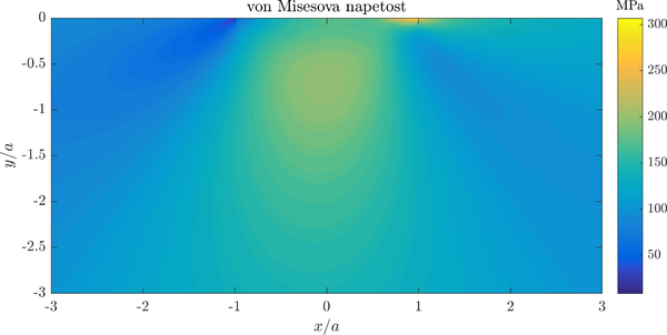
A contour plot of von Mises stress in the specimen is presented below.
Note that contour of stress are similar to the ones in Hertzian contact above, but a significant concentracion of stresses under the contact area is present.
References
- ↑ 1.0 1.1 1.2 K. Pereira et al., On the convergence of stresses in fretting fatigue, Materials 9(8) (2016), doi:10.3390/ma9080639
- ↑ R. Hojjati-Talemi, M. A. Wahab in dr., Prediction of fretting fatigue crack initiation and propagation lifetime for cylindrical contact configuration, Tribol. Int. 76 (2014) 73–91, doi:10.1016/j.triboint.2014.02.017.


