Difference between revisions of "Cantilever beam"
(→FreeFem++) |
(→Numerical solution) |
||
| Line 54: | Line 54: | ||
// Parameters | // Parameters | ||
real E = 3.0e7, nu = 0.3; | real E = 3.0e7, nu = 0.3; | ||
| − | real P = -1000 | + | real P = -1000; |
real L = 48, D = 12; | real L = 48, D = 12; | ||
real I = D^3/12; | real I = D^3/12; | ||
| Line 87: | Line 87: | ||
int2d(Th)(lambda*div(u)*div(v) + 2*mu*(eM(u)'*eM(v))) | int2d(Th)(lambda*div(u)*div(v) + 2*mu*(eM(u)'*eM(v))) | ||
- int1d(Th,4)([0,-ty]'*v) | - int1d(Th,4)([0,-ty]'*v) | ||
| − | + on(2, | + | + on(2,ux=uxb,uy=uyb); |
// Plot solution | // Plot solution | ||
real coef = 1000; | real coef = 1000; | ||
Th = movemesh(Th,[x+ux*coef,y+uy*coef]); | Th = movemesh(Th,[x+ux*coef,y+uy*coef]); | ||
| − | + | plot(Th,wait=1); | |
| − | |||
| − | plot(Th | ||
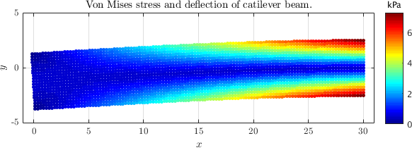
The numerical solutions for beam displacements $u_y(x,0)$ in the axial direction of the beam, and shear stresses $\sigma_{xy}(L/2,y)$ in a cross section at the half lengthwise of the beam, obtained by quadratic finite elements are shown in the figure below. Analytic solutions are shown with continuous lines. | The numerical solutions for beam displacements $u_y(x,0)$ in the axial direction of the beam, and shear stresses $\sigma_{xy}(L/2,y)$ in a cross section at the half lengthwise of the beam, obtained by quadratic finite elements are shown in the figure below. Analytic solutions are shown with continuous lines. | ||
[[File:cantilever_beam.png|800px]] | [[File:cantilever_beam.png|800px]] | ||
Revision as of 13:42, 14 November 2016
Do you want to go back to Solid Mechanics?
On this page we conduct numerical studies of bending of a cantilever loaded at the end, a common numerical benchmark in elastostatics.
Exact solution
The exact solutions to this problem is given in Timoshenko (1951) where it derived for plane stress conditions. Consider a beam of dimensions $L \times D$ having a narrow rectangular cross section. The origin of the coordinate system is placed at $(x,y) = (0,D/2)$. The beam is bent by a force $P$ applied at the end $x = 0$ and the other end of the beam is fixed (at $x = L$). The stresses in such a beam are given as: \begin{equation} \sigma_{xx} = -\frac{Pxy}{I}, \end{equation} \begin{equation} \sigma_{yy} = 0, \end{equation} \begin{equation}\label{eq:sxy} \sigma_{xy} = -\frac{P}{2I}\left(\left(\frac{D}{2}\right)^2 - y^2 \right), \end{equation} where $I = D^3/12$ is the moment of inertia.
The exact solution in terms of the displacements in $x$- and $y-$ direction is \begin{align}\label{eq:beam_a1} u_x(x,y) &= -\frac{Py}{6EI}\left(3(x^2-L^2) -(2+\nu)y^2 + 6 (1+\nu) \frac{D^2}{4}\right) \\ \label{eq:beam_a2} u_y(x,y) &= \frac{P}{6EI}\left(3\nu x y^2 + x^3 - 3L^2 x + 2L^3\right) \end{align} where $E$ is Young's modulus and $\nu$ is the Poisson ratio.
Numerical solution
For the numerical solution we first choose the following parameters:
- Loading: $P = -1000$ N
- Young's modulus: $E = 3 \times 10^7$ N/m2
- Poisson's ratio: $\nu = 0.3$
- Height of the beam: $D = 12$ m
- Length of the beam: $L = 48$ m
The unloaded beam is discretized with $40 \times 10$ regular nodes. Since the right end of the beam at $x = L$ is fixed, the displacement boundary conditions are prescribed from the known analytical formulae (\ref{eq:beam_a1}) and (\ref{eq:beam_a2}) : \begin{equation} u_x(L,y) = -\frac{P}{6EI}\left(-(2+\nu)y^2 + 6 (1+\nu) \frac{D^2}{4}\right); \qquad u_y(L,y) = \frac{P}{2EI}(\nu L y^2) \end{equation} The traction boundary at the left end of the beam ($x=0$) is given by (\ref{eq:sxy}): \begin{equation}\label{eq:trac_a} t_y(L,y) = -\frac{P}{2I}\left(\left(\frac{D}{2}\right)^2 - y^2 \right). \end{equation}
An indicator of the accuracy that can be employed is the strain energy error $e$: \begin{equation} e = \left[ \frac{1}{2} \int_\Omega (\b{\varepsilon}^\mathrm{num} - \b{\varepsilon}^\mathrm{exact})\b{C}(\b{\varepsilon}^\mathrm{num} - \b{\varepsilon}^\mathrm{exact}) d\Omega\right]^{1/2} \end{equation} where $\b{\varepsilon}$ is the strain tensor in vector form, $\b{C}$ the reduced stiffness tensor (a matrix) and $\Omega$ the domain of the calculated solution.
FreeFem++
The required code to solve this problem in FreeFem++ is
// Parameters
real E = 3.0e7, nu = 0.3;
real P = -1000;
real L = 48, D = 12;
real I = D^3/12;

// Mesh
mesh Th = square(40,10,[L*x,-D/2+D*y]);

// Macros
macro u [ux,uy] // displacement
macro v [vx,vy] // test function
macro div(u) (dx(u[0])+dy(u[1])) // divergence
macro eM(u) [dx(u[0]), dy(u[1]), sqrt(2)*(dx(u[1]) + dy(u[0]))/2] // strain tensor

// Finite element space
fespace Vh(Th,[P2,P2]);
Vh u, v;

// Boundary conditions
func uxb = -P*y/(6*E*I)*(nu*y^2-2*(1+nu)*y^2+6*D^2/4*(1+nu));
func uyb = P/(6*E*I)*(3*nu*L*y^2);
func ty = -P/(2*I)*(D^2/4-y^2);

// Convert E and nu to plane stress
E = E/(1-nu^2); nu = nu/(1-nu);

// Lame parameters
real mu = E/(2*(1+nu));
real lambda = E*nu/((1+nu)*(1-2*nu));

// Solve problem
solve cantileverBeam(u,v) =
   int2d(Th)(lambda*div(u)*div(v) + 2*mu*(eM(u)'*eM(v)))
   - int1d(Th,4)([0,-ty]'*v)
   + on(2,ux=uxb,uy=uyb);

// Plot solution
real coef = 1000;
Th = movemesh(Th,[x+ux*coef,y+uy*coef]);
plot(Th,wait=1);
The numerical solutions for beam displacements $u_y(x,0)$ in the axial direction of the beam, and shear stresses $\sigma_{xy}(L/2,y)$ in a cross section at the half lengthwise of the beam, obtained by quadratic finite elements are shown in the figure below. Analytic solutions are shown with continuous lines.
