Difference between revisions of "Hertzian contact"
(→FreeFem++ numerical solution) |
E6WikiAdmin (talk | contribs) |
||
| (83 intermediate revisions by 5 users not shown) | |||
| Line 1: | Line 1: | ||
| + | {{Box-round|title= Related papers | | ||
| + | [https://e6.ijs.si/ParallelAndDistributedSystems/publications/32230439.pdf J. Slak, G. Kosec; Adaptive radial basis function-generated finite differences method for contact problems, International journal for numerical methods in engineering, vol. 119, 2019 [DOI: 10.1002/nme.6067]] | ||
| + | }} | ||
| + | |||
| + | |||
Click on [[Solid Mechanics]] to go back. | Click on [[Solid Mechanics]] to go back. | ||
| Line 26: | Line 31: | ||
\end{equation} | \end{equation} | ||
| − | The coordinate $x$ is measured perpendicular to that of the cylinder axes. | + | The coordinate $x$ is measured perpendicular to that of the cylinder axes. The cylinder is pressing on the lower halfplane from above. Analytical solutions for stresses in the plane are presented below. |
| + | The coordinate ranges are $x \in (-\infty, \infty), z\in (-\infty, 0]$. | ||
The surface stresses are given in the following equations. At the contact interface | The surface stresses are given in the following equations. At the contact interface | ||
| Line 34: | Line 40: | ||
outside the contact region all the stress components at the surface are zero. Along the line of symmetry the following equations hold | outside the contact region all the stress components at the surface are zero. Along the line of symmetry the following equations hold | ||
\begin{equation} | \begin{equation} | ||
| − | \sigma_{xx} = - | + | \sigma_{xx} = -p_0\left( \frac{1+(z/b)^2}{\sqrt{1+(z/b)^2}} + 2z/b\right) |
\end{equation} | \end{equation} | ||
\begin{equation} | \begin{equation} | ||
| − | \sigma_{zz} = - | + | \sigma_{zz} = -p_0(1 + z^2/b^2)^{-1/2} |
\end{equation} | \end{equation} | ||
These are the principal stresses so that the principal shear stress $\tau_1$ is given by | These are the principal stresses so that the principal shear stress $\tau_1$ is given by | ||
\begin{equation} | \begin{equation} | ||
| − | \tau_1 = | + | \tau_1 = -p_0\left(z/b + \frac{(z/b)^2}{\sqrt{1+(z/b)^2}}\right) |
\end{equation} | \end{equation} | ||
from which \[(\tau_1)_\mathrm{max} = 0.30p_0, \quad \text{at } z = 0.78b\] | from which \[(\tau_1)_\mathrm{max} = 0.30p_0, \quad \text{at } z = 0.78b\] | ||
| − | Note that these stresses are all independent of Poisson's ratio although, for plane strain, the third principal stress \[\sigma_{yy} = \nu(\sigma_{xx} + \sigma_{zz})\] | + | Note that these stresses are all independent of Poisson's ratio although, for plane strain, the third principal stress \[\sigma_{yy} = \nu(\sigma_{xx} + \sigma_{zz}). \] |
| − | The surface stresses and subsurface stresses along the axis of symmetry are shown in the following two graphs. The $x$ and $z$ coordinates are normalized with the contact width $b$. | + | <!-- The surface stresses and subsurface stresses along the axis of symmetry are shown in the following two graphs. The $x$ and $z$ coordinates are normalized with the contact width $b$. |
| − | [[File:Screenshot_2016-11-16_16-13-26.png|300px]] [[File:Screenshot_2016-11-16_16-12-32.png|300px]] | + | [[File:Screenshot_2016-11-16_16-13-26.png|300px]] [[File:Screenshot_2016-11-16_16-12-32.png|300px]] --> |
At a general point $(x,z)$ the stresses may be expressed in terms of $m$ and $n$, defined by | At a general point $(x,z)$ the stresses may be expressed in terms of $m$ and $n$, defined by | ||
\begin{equation} | \begin{equation} | ||
| − | m^2 = \frac{1}{2}\left | + | m^2 = \frac{1}{2} \left(\sqrt{\left(b^2-x^2+z^2\right)^2+4 x^2 z^2}+b^2-x^2+z^2\right) |
\end{equation} | \end{equation} | ||
\begin{equation} | \begin{equation} | ||
| − | n^2 = \frac{1}{2}\left | + | n^2 = \frac{1}{2} \left(\sqrt{\left(b^2-x^2+z^2\right)^2+4 x^2 z^2}-(b^2-x^2+z^2)\right) |
\end{equation} | \end{equation} | ||
| − | + | with $m = +\sqrt{m^2}$ and $n = \operatorname{sgn}(x)\sqrt{n^2}$. | |
Whereupon | Whereupon | ||
\begin{equation} | \begin{equation} | ||
| − | \sigma_{xx} = -\frac{p_0}{b}\left[m\left(1 + \frac{z^2 + n^2}{m^2 + n^2}\right) | + | \sigma_{xx} = -\frac{p_0}{b}\left[m\left(1 + \frac{z^2 + n^2}{m^2 + n^2}\right)+2z\right] |
\end{equation} | \end{equation} | ||
\begin{equation} | \begin{equation} | ||
| − | \sigma_{ | + | \sigma_{zz} = -\frac{p_0}{b}m\left(1 - \frac{z^2 + n^2}{m^2 + n^2}\right) |
\end{equation} | \end{equation} | ||
\begin{equation} | \begin{equation} | ||
| − | \sigma_{xz} = \sigma_{ | + | \sigma_{xz} = \sigma_{zx} = \frac{p_0}{b}n\left(\frac{m^2 - z^2}{m^2 + n^2}\right) |
\end{equation} | \end{equation} | ||
| − | = | + | Plots of this analytical solution are presented below, using $p_0 = 8.36\cdot10^{7}, b = 4.13\cdot10^{-4}$ |
| + | |||
| + | [[File:divs_hertzian_analytical.png|600px]] | ||
| + | |||
| + | [[File:sxx_hertzian_analytical.png|600px]][[File:syy_hertzian_analytical.png|600px]] | ||
| − | + | [[File:sxy_hertzian_analytical.png|600px]][[File:psd_hertzian_analytical.png|600px]] | |
| − | + | The solutions were verified and graphs were generated using this mathematica notebook: [[:File:hertzian_analytical.nb]] | |
| − | + | ||
| − | + | Copy-pasteable Matlab code of the analytical solution: | |
| − | - | + | <syntaxhighlight lang="matlab" line> |
| − | + | function [sxx, syy, sxy] = analytical(x, z, b, p0) | |
| − | + | % Returns the analytical solution for stress for hertzian contact. | |
| − | + | % x in (-inf, inf), z in (-inf, 0]. | |
| − | + | bxz = b^2 - x.^2 + z.^2; | |
| − | + | xz = 4*x.^2.*z.^2; | |
| − | + | koren = sqrt(bxz.^2 + xz); | |
| − | + | m2 = 1/2 * (koren + bxz); | |
| + | n2 = 1/2 * (koren - bxz); | ||
| + | m = sqrt(m2); | ||
| + | n = sign(x) .* sqrt(n2); | ||
| + | mpn = m2 + n2; | ||
| + | zmn = (z.^2 + n2) ./ mpn; | ||
| + | sxx = -p0 / b * (m .* (1 + zmn) + 2*z); | ||
| + | syy = -p0 / b * m .* (1 - zmn); | ||
| + | sxy = p0 / b * n .* ((m2 - z.^2) ./ mpn); | ||
| + | end | ||
| + | </syntaxhighlight> | ||
| − | + | Copy-pasteable C++ code of the analytical solution: | |
| − | + | <syntaxhighlight lang="c++" line> | |
| + | std::function<Vec3d(Vec2d)> analytical = [=] (const Vec2d& p) { | ||
| + | double x = p[0], z = p[1]; | ||
| + | double bxz = b*b - x*x + z*z; | ||
| + | double xz = 4*x*x*z*z; | ||
| + | double koren = std::sqrt(bxz*bxz + xz); | ||
| + | double m2 = 0.5 * (koren + bxz); | ||
| + | double n2 = 0.5 * (koren - bxz); | ||
| + | double m = std::sqrt(m2); | ||
| + | double n = signum(x) * std::sqrt(n2); | ||
| + | double mpn = m2 + n2; | ||
| + | double zmn = (z*z + n2) / mpn; | ||
| + | double sxx = -p0 / b * (m * (1 + zmn) + 2*z); | ||
| + | double syy = -p0 / b * m * (1 - zmn); | ||
| + | double sxy = p0 / b * n * ((m2 - z*z) / mpn); | ||
| + | return Vec3d(sxx, syy, sxy); | ||
| + | }; | ||
| + | </syntaxhighlight> | ||
| + | The extreme of $\tau_1$ is achieved at $x = 0$, $z = -\sqrt{\frac{1}{2} \left(\sqrt{5}-1\right)} b = -0.786b$. | ||
| − | + | [[File:midplane_stress_hertzian_analytical.png|600px]] [[File:taumax_stress_hertzian_analytical.png|600px]] | |
| − | + | When observing for $z \to -\infty$ it holds that | |
| + | $s_{xx} = \frac{\frac{b^3 p_0}{4}+b p_0 x^2}{z^3}+O(z^{-5})$, | ||
| + | $s_{zz} = \frac{b p_0}{z}-\frac{b p_0 \left(b^2+4 x^2\right)}{2 z^3}+O(z^{-5})$, | ||
| + | $s_{xz} = \frac{b p_0 x}{z^2}+\frac{-\frac{3}{2} b^3 p_0 x-2 b p_0 x^3}{z^4}+O(z^{-5})$. | ||
| − | + | When observing for $x \to \infty$ (and similarly for $-\infty$) it holds that | |
| − | + | $s_{xx} = \frac{b p_0 z}{x^2}+\frac{\frac{3}{4} b^3 p_0 z-2 b p_0 z^3}{x^4}+O(x^{-5})$, | |
| − | \ | + | $s_{zz} = \frac{b p_0 z^3}{x^4}+O(x^{-5})$, |
| − | + | $s_{xz} = \frac{b p_0 z^2}{x^3}+O(x^{-5})$. | |
| − | |||
| − | |||
| − | |||
| − | |||
| − | |||
| − | |||
| − | |||
| − | |||
| − | |||
| − | |||
= FreeFem++ numerical solution = | = FreeFem++ numerical solution = | ||
| − | For the numerical solution in FreeFem++ we choose parameters similar to those in Pereira et al. (2016): <ref> Pereira et al. | + | For the numerical solution in FreeFem++ we choose parameters similar to those in Pereira et al. (2016): <ref> K. Pereira et al., On the convergence of stresses in fretting fatigue, Materials |
| + | 9(8) (2016), doi:10.3390/ma9080639. </ref> | ||
*Modulus of elasticity: $E = 72.1$ GPa | *Modulus of elasticity: $E = 72.1$ GPa | ||
| Line 123: | Line 155: | ||
*Specimen length: $L = 40$ mm | *Specimen length: $L = 40$ mm | ||
*Specimen height: $H = 10$ mm | *Specimen height: $H = 10$ mm | ||
| + | *Specimen thickness: $t = 4$ mm | ||
We assume that both the pad and specimen are from the same material, therefore the combined modulus is \[E^* = \frac{E}{2(1-\nu^2)}.\] According to Pereira et al. (2016) contact width is now defined with the specimen height in the denominator: | We assume that both the pad and specimen are from the same material, therefore the combined modulus is \[E^* = \frac{E}{2(1-\nu^2)}.\] According to Pereira et al. (2016) contact width is now defined with the specimen height in the denominator: | ||
| − | \[b = 2\sqrt{\frac{PR}{ | + | \[b = 2\sqrt{\frac{PR}{t\pi E^*}}\] |
| − | \[p_0 = \sqrt{\frac{PE^*}{ | + | \[p_0 = \sqrt{\frac{PE^*}{t\pi R}}\] |
| − | |||
| − | Out of simplicity we only use traction boundaries at the top surface. On the left, right and bottom sides of the specimen Dirichlet boundaries are used. The center of the coordinate system is placed at $(x,y) = (L/2,0)$. The axises therefore go from $-L/2$ to $L/2$ in $x$-direction and from $ | + | Out of simplicity we only use traction boundaries at the top surface. On the left, right and bottom sides of the specimen Dirichlet boundaries are used. The center of the coordinate system is placed at $(x,y) = (L/2,0)$. The axises therefore go from $-L/2$ to $L/2$ in $x$-direction and from $0$ to $H$ in $y$-direction. |
top | top | ||
| Line 154: | Line 186: | ||
\] | \] | ||
| − | The numerical solution is obtained for plane '''strain''' conditions. | + | The numerical solution is obtained for plane '''strain''' conditions using quadratic finite elements. The final mesh after adaptation had ~$40000$ dof. The images below show the raw values of the surface stresses, sub-surface stresses along the axis of symmetry and a close-up of the maximum shear stress contours close to the contact. The contact width $b \approx 0.29$ mm for the parameters described at the beginning of this section. |
| + | |||
| + | [[File:surface_stress.png|600px]] | ||
| + | |||
| + | [[File:subsurface_stress.png|500px]] | ||
| + | |||
| + | [[File:mss_contours.png|900px]] | ||
| + | |||
| + | = Meshless numerical solution for halfplane contact = | ||
| + | We are solving the equation $$(\lambda + \mu) \nabla (\nabla \cdot \b{u}) + \mu \nabla^2 \b{u} = 0$$ | ||
| + | |||
| + | The boundary conditions are zero except for the top layer which has zero traction in $x$ direction and traction $t_z$ in $z$ direction. | ||
| + | |||
| + | * top: $\vec{t}(x) = (0, -p(x))$ or componentwise $(2 \mu+\lambda) \frac{\partial u}{\partial x}(x, 0) + \lambda \frac{\partial v}{\partial y}(x, 0) = -p(x)$ and $\mu \frac{\partial u}{\partial y}(x, 0) + \mu \frac{\partial v}{\partial x}(x, 0) = 0$. | ||
| + | * bottom, left, right: $\vec{u}=0$ | ||
| + | Problem parameters used: | ||
| + | *Modulus of elasticity: $E = 72.1$ GPa | ||
| + | *Poisson's ratio: $\nu = 0.33$ | ||
| + | *Normal load: $P = 543$ N | ||
| + | *Cylinder radius: $R = 1$ m | ||
| + | *Specimen height: $H = 10$ mm | ||
| + | *Specimen length: $L = 2H = 20$ mm | ||
| + | |||
| + | Convergence with respect to uniform mesh is very bumpy, due to very few nodes (max. 100) actually being under the contact surface. | ||
| + | |||
| + | [[File:hertzian_convergence.png|600px]] | ||
| + | |||
| + | Much more can be achieved with refinement. Taking $H = 1$ m $\approx 75\,000\,b$ and refining the domain around the contact region. | ||
| + | Refined domain is presented below, along tiwh the refinement density. | ||
| + | |||
| + | [[File:hertzian_refined_domain.png|600px]][[File:hertzian_refined_domain_density.png|600px]] | ||
| + | |||
| + | Convergence with respect to different refine levels is shown below. | ||
| + | |||
| + | [[File:hertzian_refine_levels_convergence.png|600px]] | ||
| + | |||
| + | The convergence is more regular than before and every additional level greatly helps regarding the total error. | ||
| + | The solution with the smallest error is shown below. | ||
| + | |||
| + | [[File:hertzian_solution_deformed_vm.png|600px]] | ||
| + | |||
| + | Execution time is shown below. Program ran on a single core. Most of the time is spent on solving the system of the equations. | ||
| + | |||
| + | [[File:hertzian_time.png|800px]] | ||
| + | |||
| + | <!-- | ||
| + | |||
| + | [[File:hertzian_subsurface_nonrefined.png|800px]] | ||
| + | |||
| + | [[File:hertzian_midplane_nonrefined.png|800px]] | ||
| + | |||
| + | The error decreases as the density of nodes increases, up to some limit when the system becomes too unstable. | ||
| + | |||
| + | [[File:hertzian_error_nonrefined_convergence.png|800px]] | ||
| + | |||
| + | More can be gained using refinement: | ||
| + | |||
| + | [[File:hertzian_midplane_refined.png|800px]] | ||
| + | |||
| + | [[File:hertzian_subsurface_refined.png|800px]] | ||
| + | |||
| + | [[File:hertzian_domain_refined.png|800px]] | ||
| + | |||
| + | [[File:hertzian_psd_contour_refined.png|800px]] --> | ||
=References= | =References= | ||
<references/> | <references/> | ||
Latest revision as of 20:57, 22 October 2022
Related papers
Click on Solid Mechanics to go back.
Contact of Cylinders - the Hertz problem
Detailed discussions of this problem can be found in Hills and Nowells (1994) as well as Williams and Dwyer-Joyce (2001). [1] [2]
If two circular cylinders with radii $R_1$ and $R_2$ are pressed together by a force per unit length of magnitude $P$ with their axes parallel, then the contact patch will be of half-width $b$ such that \begin{equation} b = 2\sqrt{\frac{PR}{\pi E^*}} \end{equation} where $R$ and $E^*$ are the reduced radius of contact and the contact modulus defined by \begin{equation} \frac{1}{R} = \frac{1}{R_1} + \frac{1}{R_2}, \end{equation} \begin{equation} \frac{1}{E^*} = \frac{1-{\nu_1}^2}{E_1} + \frac{1-{\nu_2}^2}{E_2}. \end{equation}
The resulting pressure distribution $p(x)$ is semielliptical, i.e., of the form \begin{equation} p(x) = p_0 \sqrt{1-\frac{x^2}{b^2}} \end{equation} where the peak pressure \begin{equation} p_0 = \sqrt{\frac{PE^*}{\pi R}}. \end{equation}
The coordinate $x$ is measured perpendicular to that of the cylinder axes. The cylinder is pressing on the lower halfplane from above. Analytical solutions for stresses in the plane are presented below. The coordinate ranges are $x \in (-\infty, \infty), z\in (-\infty, 0]$.
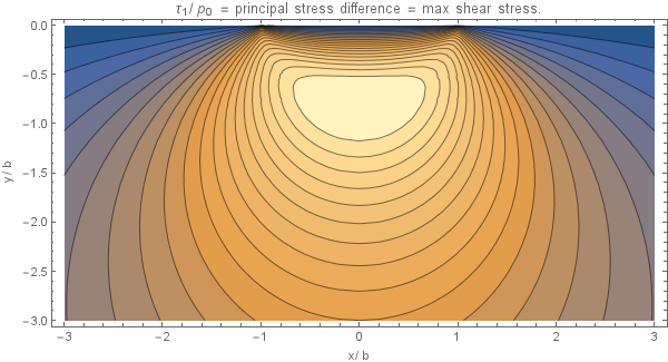
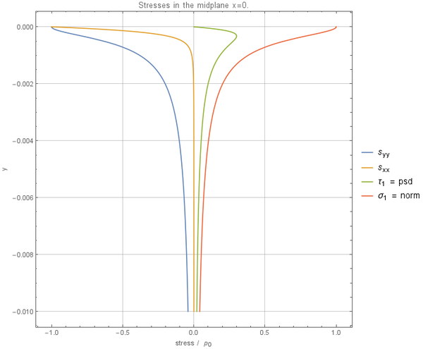
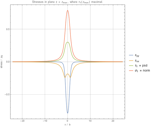
The surface stresses are given in the following equations. At the contact interface \begin{equation} \sigma_{xx} = \sigma_{zz} = -p(x); \end{equation} outside the contact region all the stress components at the surface are zero. Along the line of symmetry the following equations hold \begin{equation} \sigma_{xx} = -p_0\left( \frac{1+(z/b)^2}{\sqrt{1+(z/b)^2}} + 2z/b\right) \end{equation} \begin{equation} \sigma_{zz} = -p_0(1 + z^2/b^2)^{-1/2} \end{equation} These are the principal stresses so that the principal shear stress $\tau_1$ is given by \begin{equation} \tau_1 = -p_0\left(z/b + \frac{(z/b)^2}{\sqrt{1+(z/b)^2}}\right) \end{equation} from which \[(\tau_1)_\mathrm{max} = 0.30p_0, \quad \text{at } z = 0.78b\]
Note that these stresses are all independent of Poisson's ratio although, for plane strain, the third principal stress \[\sigma_{yy} = \nu(\sigma_{xx} + \sigma_{zz}). \]
At a general point $(x,z)$ the stresses may be expressed in terms of $m$ and $n$, defined by
\begin{equation}
m^2 = \frac{1}{2} \left(\sqrt{\left(b^2-x^2+z^2\right)^2+4 x^2 z^2}+b^2-x^2+z^2\right)
\end{equation}
\begin{equation}
n^2 = \frac{1}{2} \left(\sqrt{\left(b^2-x^2+z^2\right)^2+4 x^2 z^2}-(b^2-x^2+z^2)\right)
\end{equation}
with $m = +\sqrt{m^2}$ and $n = \operatorname{sgn}(x)\sqrt{n^2}$.
Whereupon
\begin{equation}
\sigma_{xx} = -\frac{p_0}{b}\left[m\left(1 + \frac{z^2 + n^2}{m^2 + n^2}\right)+2z\right]
\end{equation}
\begin{equation} \sigma_{zz} = -\frac{p_0}{b}m\left(1 - \frac{z^2 + n^2}{m^2 + n^2}\right) \end{equation}
\begin{equation} \sigma_{xz} = \sigma_{zx} = \frac{p_0}{b}n\left(\frac{m^2 - z^2}{m^2 + n^2}\right) \end{equation}
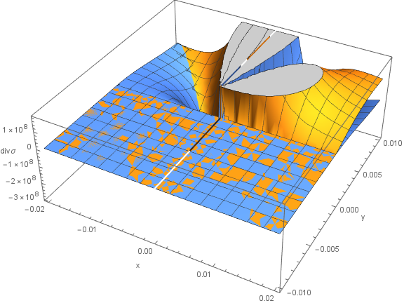
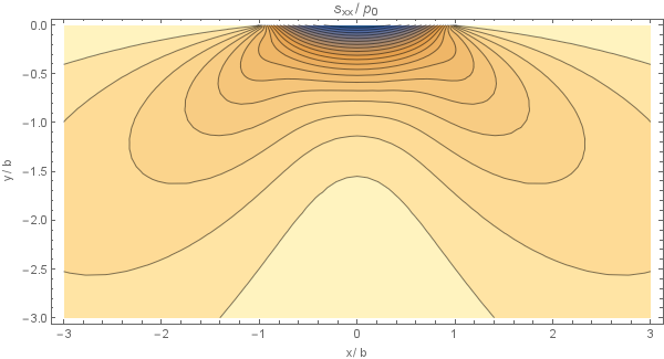
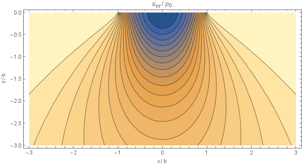
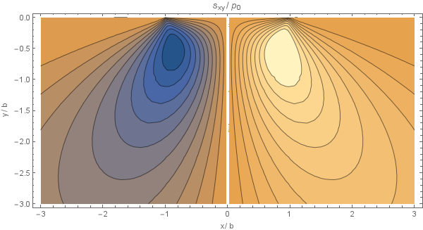
Plots of this analytical solution are presented below, using $p_0 = 8.36\cdot10^{7}, b = 4.13\cdot10^{-4}$
The solutions were verified and graphs were generated using this mathematica notebook: File:hertzian_analytical.nb
Copy-pasteable Matlab code of the analytical solution:
 1 function [sxx, syy, sxy] = analytical(x, z, b, p0)
 2 % Returns the analytical solution for stress for hertzian contact.
 3 % x in (-inf, inf), z in (-inf, 0].
 4 bxz = b^2 - x.^2 + z.^2;
 5 xz = 4*x.^2.*z.^2;
 6 koren = sqrt(bxz.^2 + xz);
 7 m2 = 1/2 * (koren + bxz);
 8 n2 = 1/2 * (koren - bxz);
 9 m = sqrt(m2);
10 n = sign(x) .* sqrt(n2);
11 mpn = m2 + n2;
12 zmn = (z.^2 + n2) ./ mpn;
13 sxx = -p0 / b * (m .* (1 + zmn) + 2*z);
14 syy = -p0 / b * m .* (1 - zmn);
15 sxy = p0 / b * n .* ((m2 - z.^2) ./ mpn);
16 end
Copy-pasteable C++ code of the analytical solution:
 1 std::function<Vec3d(Vec2d)> analytical = [=] (const Vec2d& p) {
 2     double x = p[0], z = p[1];
 3     double bxz = b*b - x*x + z*z;
 4     double xz = 4*x*x*z*z;
 5     double koren = std::sqrt(bxz*bxz + xz);
 6     double m2 = 0.5 * (koren + bxz);
 7     double n2 = 0.5 * (koren - bxz);
 8     double m = std::sqrt(m2);
 9     double n = signum(x) * std::sqrt(n2);
10     double mpn = m2 + n2;
11     double zmn = (z*z + n2) / mpn;
12     double sxx = -p0 / b * (m * (1 + zmn) + 2*z);
13     double syy = -p0 / b * m * (1 - zmn);
14     double sxy = p0 / b * n * ((m2 - z*z) / mpn);
15     return Vec3d(sxx, syy, sxy);
16 };
The extreme of $\tau_1$ is achieved at $x = 0$, $z = -\sqrt{\frac{1}{2} \left(\sqrt{5}-1\right)} b = -0.786b$.
When observing for $z \to -\infty$ it holds that $s_{xx} = \frac{\frac{b^3 p_0}{4}+b p_0 x^2}{z^3}+O(z^{-5})$, $s_{zz} = \frac{b p_0}{z}-\frac{b p_0 \left(b^2+4 x^2\right)}{2 z^3}+O(z^{-5})$, $s_{xz} = \frac{b p_0 x}{z^2}+\frac{-\frac{3}{2} b^3 p_0 x-2 b p_0 x^3}{z^4}+O(z^{-5})$.
When observing for $x \to \infty$ (and similarly for $-\infty$) it holds that
$s_{xx} = \frac{b p_0 z}{x^2}+\frac{\frac{3}{4} b^3 p_0 z-2 b p_0 z^3}{x^4}+O(x^{-5})$, $s_{zz} = \frac{b p_0 z^3}{x^4}+O(x^{-5})$, $s_{xz} = \frac{b p_0 z^2}{x^3}+O(x^{-5})$.
FreeFem++ numerical solution
For the numerical solution in FreeFem++ we choose parameters similar to those in Pereira et al. (2016): [3]
- Modulus of elasticity: $E = 72.1$ GPa
- Poisson's ratio: $\nu = 0.33$
- Normal load: $P = 543$ N
- Coefficient of friction: $\mu = 0.85$
- Cylinder radius: $R = 50$ mm
- Specimen length: $L = 40$ mm
- Specimen height: $H = 10$ mm
- Specimen thickness: $t = 4$ mm
We assume that both the pad and specimen are from the same material, therefore the combined modulus is \[E^* = \frac{E}{2(1-\nu^2)}.\] According to Pereira et al. (2016) contact width is now defined with the specimen height in the denominator: \[b = 2\sqrt{\frac{PR}{t\pi E^*}}\] \[p_0 = \sqrt{\frac{PE^*}{t\pi R}}\]
Out of simplicity we only use traction boundaries at the top surface. On the left, right and bottom sides of the specimen Dirichlet boundaries are used. The center of the coordinate system is placed at $(x,y) = (L/2,0)$. The axises therefore go from $-L/2$ to $L/2$ in $x$-direction and from $0$ to $H$ in $y$-direction.
                top
      ________________________
     |                        |
     |                        |
left |                        | right
     |                        |
     |________________________|

               bottom
Boundary conditions: \[ t_z(x) = \begin{cases} -p_0\sqrt{1 - \frac{x^2}{b^2}}, \quad |x| \leq b \\ 0, \quad \text{otherwise} \end{cases} \quad \text{on } \Gamma_\mathrm{top} \] \[ (u_x,u_z) = (0,0) \quad \text{on } \Gamma_\mathrm{left},\Gamma_\mathrm{right},\Gamma_\mathrm{bottom} \]
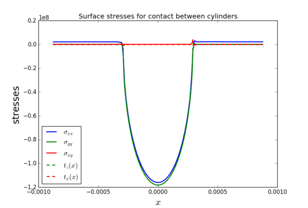
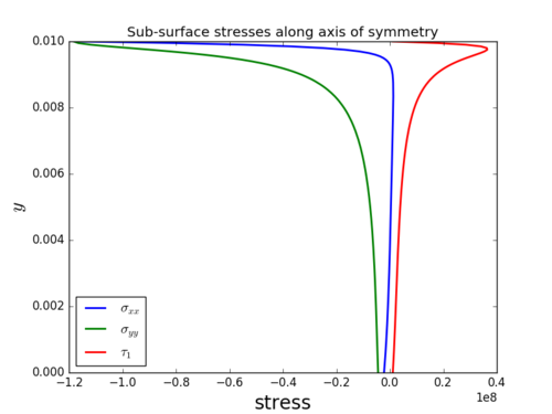
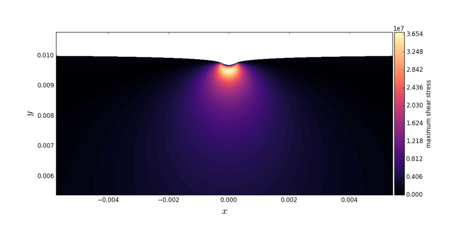
The numerical solution is obtained for plane strain conditions using quadratic finite elements. The final mesh after adaptation had ~$40000$ dof. The images below show the raw values of the surface stresses, sub-surface stresses along the axis of symmetry and a close-up of the maximum shear stress contours close to the contact. The contact width $b \approx 0.29$ mm for the parameters described at the beginning of this section.
Meshless numerical solution for halfplane contact
We are solving the equation $$(\lambda + \mu) \nabla (\nabla \cdot \b{u}) + \mu \nabla^2 \b{u} = 0$$
The boundary conditions are zero except for the top layer which has zero traction in $x$ direction and traction $t_z$ in $z$ direction.
- top: $\vec{t}(x) = (0, -p(x))$ or componentwise $(2 \mu+\lambda) \frac{\partial u}{\partial x}(x, 0) + \lambda \frac{\partial v}{\partial y}(x, 0) = -p(x)$ and $\mu \frac{\partial u}{\partial y}(x, 0) + \mu \frac{\partial v}{\partial x}(x, 0) = 0$.
- bottom, left, right: $\vec{u}=0$
Problem parameters used:
- Modulus of elasticity: $E = 72.1$ GPa
- Poisson's ratio: $\nu = 0.33$
- Normal load: $P = 543$ N
- Cylinder radius: $R = 1$ m
- Specimen height: $H = 10$ mm
- Specimen length: $L = 2H = 20$ mm
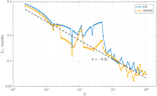
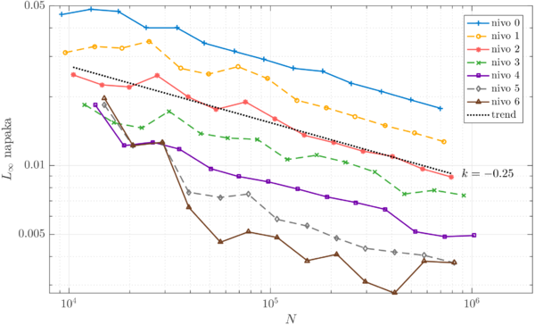
Convergence with respect to uniform mesh is very bumpy, due to very few nodes (max. 100) actually being under the contact surface.
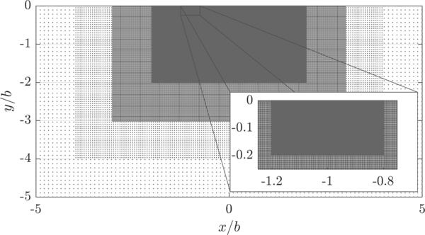
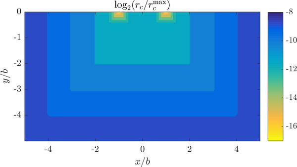
Much more can be achieved with refinement. Taking $H = 1$ m $\approx 75\,000\,b$ and refining the domain around the contact region. Refined domain is presented below, along tiwh the refinement density.
Convergence with respect to different refine levels is shown below.
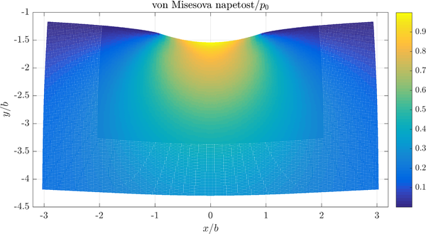
The convergence is more regular than before and every additional level greatly helps regarding the total error. The solution with the smallest error is shown below.
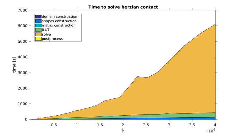
Execution time is shown below. Program ran on a single core. Most of the time is spent on solving the system of the equations.
References
- ↑ Hills, D. A. and Nowell, D. (1994). Mechanics of Fretting Fatique, p. 20-25. Springer Science+Business Media, Dordrecht.
- ↑ Williams, John A. and Dwyer-Joyce, Rob S. (2001). Contact Between Solid Surfaces, p. 121 in Modern Tribology Handbook: Volume 1, Principles of Tribology, editor: Bushan, Bharat. CRC Press LLC, Boca Raton.
- ↑ K. Pereira et al., On the convergence of stresses in fretting fatigue, Materials 9(8) (2016), doi:10.3390/ma9080639.
